
READ ME FIRST!
(757) 890-4888
Please read the entire manual BEFORE starting any
installation.
Please write down any questions and call or email
us for answers BEFORE taking apart the truck.
sales@stealthdumptrucks.com

Stealth Dump Trucks is a trademark of Stealth Dump
Trucks, Inc
Installation,
maintenance,
and
safety manual
Chevy/GMC 99-07, Over the Bumper Dumper
Stealth Dump Trucks, Inc.
(757)890-4888
Revision
1.08
© 2004-07 Stealth Dump Trucks, Inc., All rights reserved
NEVER USE IMPACT TOOLS TO INSTALL
STAINLESS BOLTS, ONLY USE HAND TOOLS WITH ANTI-SIEZE LUBE
Stealth Dump Trucks, Inc.
(757)890-4888
sales@stealthdumptrucks.com
Installation,
Maintenance, and Safety Manual
I. Safety First !
A. Preparation
for installation
1
General
Precautions: Wear appropriate safety protection for
various aspects of the installation. We
recommend clear safety glasses, leather or reinforced cotton work gloves,
safety steel toed shoes, long pants, and long sleeve shirt. The installation requires heavy lifting of
components weighing over 100 lbs., we recommend lower back support for these
tasks. Use only properly rated overhead
hoists for lifting and moving the bed.
The installation should not require jacking up the vehicle, however, if
you use a jack we recommend placing at least two jack stands under the vehicle
while you work. Various holes will need
to be drilled to mount components. Use
only properly grounded electrical tools.
Do not drill any holes without checking the back side for clearance or
obstructions. Do not drill into the fuel
tank, electrical wiring, hoses, brake or fuel lines. Do not create any sparks
near the fuel tank, filler neck, fuel vent hoses, or the battery. When the bed is raised during installation,
or maintenance, always use properly rated mechanical hoist. We recommend a secondary safety prop such as
a board or saw horses to ensure against failure of the primary hoist or
rigging. Never attempt to install this
kit alone, there should always be at least two people present. If an accident occurs, the second person can
render first aid, and/or call for help.
NEVER operate the dumping unit while parked inside a garage with a
ceiling height under 12 feet, or with overhead obstructions. Do not allow children to play in, under,
or near the bed while raised. We
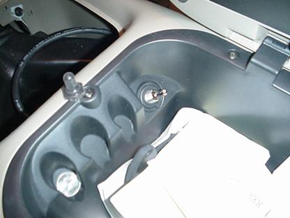
recommend installing the switch inside the lockable center console, or power
the switch from a source that requires the ignition key to be ‘ON’. Finally, the safe installation and use of
this product is the responsibility of the owner/operator. Do not alter the design or materials
used. Do not abuse, misuse, or overload
the vehicle or dump mechanism for safety implications. Dump trucks have a very high center of
gravity, always dump on level ground, never on a hillside.
2
Scope
of work and skills required for installation: This job entails
removal/installation of the pick-up truck bed, associated wire harness and fuel
filler hose. Once removed, several
components will be aligned by measurements, holes drilled, and attached by
bolts, pins, or snap rings. The installation
should be done on a hard flat surface such as a concrete floor, and indoors
where possible. Persons skilled in the
use of hand and power tools for carpentry, auto repair, electricians,
machinists, or machinery repairs should be qualified to install the kit.
B.
Specific Safety Warnings
1. Lifting, rigging, and Weights:
The bed of a truck weighs approx. 450 lbs. depending on the model. We include a chain sling with the kit that is
rated for at least 650lbs. We recommend
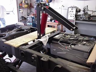
using an overhead hoist or engine hoist rated for at least one ton. A typical engine hoist is depicted in various
photographs of an installation. Wheeled
engine hoists are unstable when loaded and moving, we recommend sweeping the
floor clean to prevent wheel stops and tipping.
It’s important to have at least one person ‘spotting’ the bed while
lifting off the frame to prevent collision with the cab and paint damage. Two or three people should be used to roll
the engine hoist while loaded to prevent tipping or damage. The bed should be placed on commercially
available steel saw horses rated for 500 lbs. each. Wooden or home made sawhorses can be used,
however, they must be designed for the weight, use thru bolts, and be
stable. You will be working under the
bed while supported by these sawhorses. Never
work under the bed while only supported by the engine or overhead hoist. The elevating hinge assembly weighs 100
pounds. While working with the assembly,
do not place your hands or arms under it when elevated. There are several pinch points which act in a
scissor manner that could cause injury.
Use wood blocking to prevent the hinge from closing on hands or
arms. The scissor hoist assembly weighs
at least 73 pounds and also has pinch points.
Use wood blocking to hold the scissor while installing the pivot
pins. The lid of the Shipping Crate is
designed for this task. The
hydraulic pump weighs 31 lbs., one person should hold it in place while another
adjusts position and tightens bolts.
Use proper lifting techniques while working.
2. Electrical Safety:
Eye protection should always be worn while working near the
battery. Lead-acid batteries contain
hydrogen gas, which is extremely explosive.
Avoid any sparks or arcing by turning off the ignition key, and all
lighting such as the dome or cargo light.
Before beginning the removal of the bed, the battery should be
disconnected from the positive terminal with the engine off and cool. Use an insulated 5/16” wrench and use
care not to touch other metal components.
Wrap the cable terminal in electrical tape temporarily to avoid future
contact with the battery. When making
electrical connections, ensure they are tight and the terminal or wire does not
contact other grounded or charged components.
Protect wires against pinching, crushing, chaffing, sharp edges and hot
surfaces such as the exhaust system.
Utilize tie wraps and electrical tape to ensure against strain or
vibrations causing loosening or disconnections.
When first energizing the hydraulic pump, have a wrench available to
disconnect the battery should the pump or wiring be defective or connected
incorrectly. If you are not
qualified to work on electrical systems, or feel uncomfortable, please contact
a local electrician for assistance.
3. Fuel System Safety: Gasoline
vapors are explosive, do not smoke or create sparks while working on the fuel
system. Modification to the filler neck
hose should be performed outdoors, not in an enclosed garage where
vapors may accumulate. The battery
should be disconnected before working on the fuel system, and the engine
cool. We recommend the fuel tank be under
¾ full before starting this task. Have
proper fire extinguishing equipment available in case of accident.
Detailed Installation Instructions
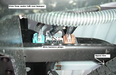
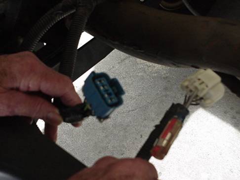
A. Removal Of the Truck Bed
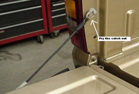
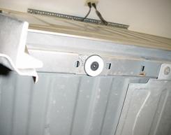
1. Electrical system: Disconnect the battery with the truck off and cool. Under the left rear area of the bed there is a junction plate for the electrical plugs from the tail & bumper lights. Trace the wires to the proper plugs. These plugs are removed by inserting a small regular screwdriver into the slot to release the catch, then pull. See photo’s below:
Fuel Filler Neck: Using the T30 torx driver supplied in the kit, loosen two screws under the gas cap. Using a small regular screwdriver, pry up the plastic ‘push to lock’ fastener under the gas cap. Disconnect any gas cap to body retaining lanyard. Check the back side for other fasteners, pull down the filler neck out of the opening. Disconnect any grounding straps from the bed.
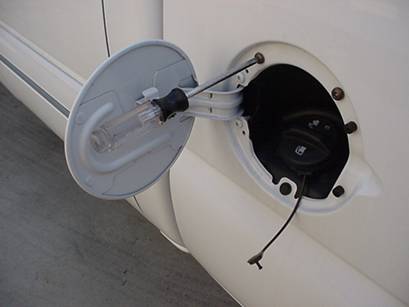
The plastic shroud surrounding the filler neck can be removed now or later once the bed is off.
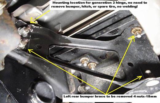
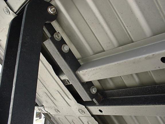
3. Frame and bumper mounts: The bed is attached to the frame by six or eight bolts. The bolts are located inside the C channel of the frame going up into the bed crossmembers. Using the 18mm socket supplied, remove all the bolts. Please wear eye protection under the truck. Place the bolts in your trucks spare tire tool bag, you may need them if you decide to reattach the bed in the future. There are 8 nuts holding the bumper wing supports to the frame. These are easier to remove with the bed off, see photo
Lifting Sling & Support: Unsnap the tailgate support cable clips and tilt out the tailgate, set aside in a safe place. Find the chain slings in the shipping crate. Attach the ends of the chains to the bed lower tie down hoops.
Attach the sling to the hoist and carefully lift the bed. Check for wiring, bolts, or hoses underneath.
Long bed trucks may require the use of a wheeled gantry and chain fall if an engine hoist won’t reach the center of the bed.
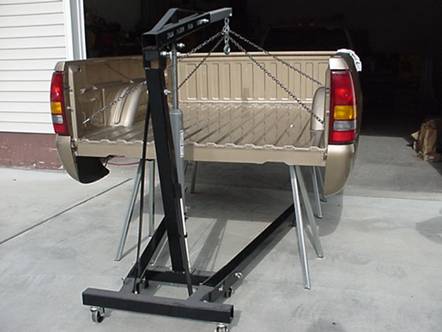
Place the bed on the sawhorses, leave the engine hoist attached for safety.
Remove the plastic shroud from the fuel filler hose. Remove the 18mm nuts on the right and left bumper wing braces if not performed earlier. Store the braces, and fasteners, they will be used.
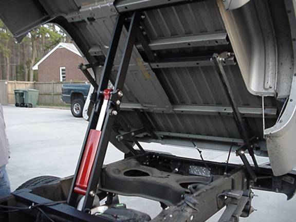
B. Installing the Over The Bumper Dumper™
1. Parts Identification and Listing: Hinge Assembly parts labeled on Diagram 1:
-------------Actual parts may differ from drawing due to
updates----------
1 Torsion Tube
2 Torsion Tube Frame Mounts (2 each) L-shape with 1” bore
3 Main Link (L-shaped rear pivot slips into rectangular tubing)
4 Rear Link, Left, Driver, Updated rear links are straight
5 Rear Link, Right, Passenger
6
Center Link (2) (Long
bed 2500-3500 center link attaches to part #2 pin)
7
Under Frame Mount (2), Right & Left for
Center Link (Omit for Long bed)
8 Front Link (2)
9 Front Link Angle Mount & Rear Bed Stiffener
10 Forward Bed Angle Stiffener
11 Center Bar Updated is rectangular square tube or two flat bars or angle iron on long bed
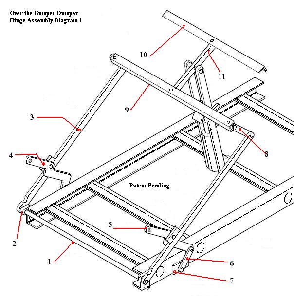
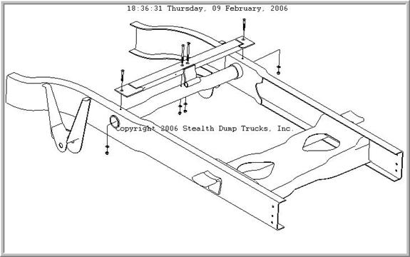
Diagram 1 for 2500-3500 Long Bed Version:
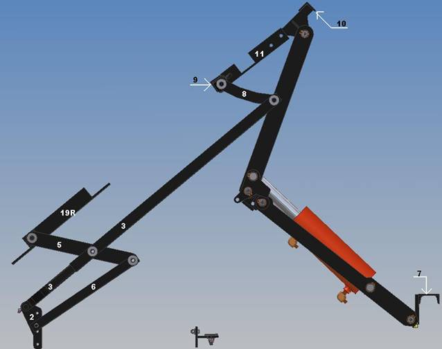
Part
7: Lower Hoist Mount, is long channel cross member referenced in the hoist
parts list.
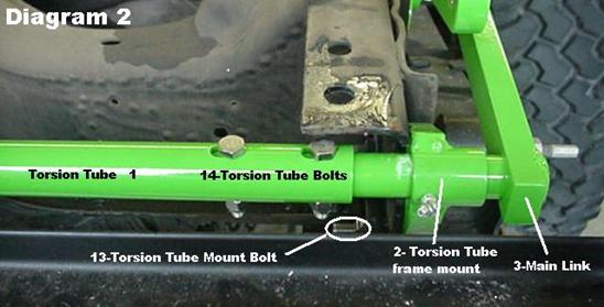
Hinge assembly parts
shown on Diagram 2:
12
Part Number omitted due
to update-not shown
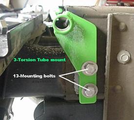
13 Torsion Tube Mount Bolts ½”-13 X 1.25” hex head (4) with washers
14 Torsion Tube Bolt 3/8” X 2” with lock nut (2)-Stainless

Hinge assembly parts
shown on Diagram 3: Updated parts will differ from diagram!
15 Stainless Steel 3/8”-16 X 3” Hex Head Bolts with washer and locknut (4) for bed stiffeners
16 Stainless 1/2”-13 X 2” with locknut (3) for Center Bar to Stiffener mounting
17 Hex head 5/8” X 2” bolt with locknut, two washers (2) for Front link to Stiffener Pivot
18 Various 5/8” stainless bolts with washers and locknuts already greased and installed in pivots
Hinge
assembly parts shown on Diagram 4: Updated parts
will differ from diagram!
19 Rear Bed Mounts, Right & Left
20 Countersunk Flat Head 12mm X 20mm bolts (4) for Rear Bed Mounts
21 Hex head 1/2” X 2” bolt with locknut, two washers and large spacer (2) for Under Frame Mount
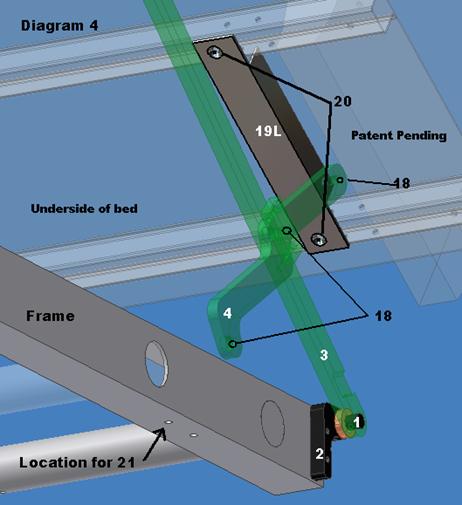
Part # 6 Center link
and Part #7 under frame mount not shown above
Long bed
will not include part #7, part # 6 will attach to welded pin on part #2
1500 Long bed
uses Part #7 under frame mount pin.
Scissor
Hoist (Short Version) assembly parts shown on Diagram 5:
1. Safety pin (shipped in parts bag)
2. Channel Hinge
3. Upper Arms, Right & Left (2)
4. Stop Block (2)
5. Lower Arms (2)
6. Hydraulic Cylinder
7. Hoist Frame Mount (Long bed version has full width cross member)
8. Upper Pivot Pin
9. Lower Pivot Pin
10. Frame Bolts 3/8”-16 X 4” with washers and locknuts (2)
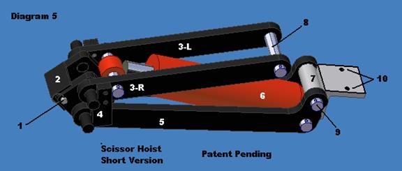
Long Version of the Scissor Hoist has longer Upper Arms,
Part # 3-R & 3-L extend over part # 7.
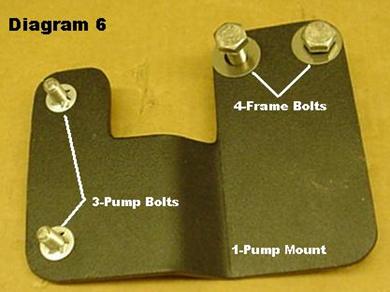
Pump
Mount assembly shown in Diagram 6: Long bed mount is mirror image of photo.
1. Pump Mounting Plate (Bolt holes for PN:4 to be drilled by customer to fit)
2. Part Number omitted with update-not shown
3.
Pump
4.
Frame
Installing the Over The Bumper Dumper
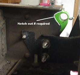
2. Torsion Tube Mount: Find the Torsion Tube Mounts, Torsion Tube Mounting Bolts, and Copper anti-seize lubricant. Test fit to truck frame as shown with long side of pipe facing out. Some trucks require a clearance notch cut on the frame for the Torsion Tube Pivot to pass thru the mount. Remove after test fit. Lightly coat the inside of the 1” bores of the mounts with lubricant.
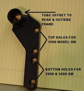
We recommend 2500 & 3500
models use the top 1500 model hole for an additional bolt by drilling the frame
while attached during test fitting. An
extra ½” bolt is included for this purpose.
There may be a rivet head protruding on top of the C-frame where the
rear cross member is attached. Grind or chisel off the rivet head closest to the bumper end
on both driver and passenger side.
These mounts will be assembled to the hinge & truck bed while off the
frame. The whole hinge assembly process
is quicker while the bed is off the truck.
Once those steps are complete the bed will be re-installed and attached
to the frame with these mounts & bolts.
NEVER USE IMPACT TOOLS ON STAINLESS BOLTS, ONLY USE HAND TOOLS WITH
ANTI-SIEZE !
3. Bed Mounts and Stiffeners
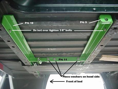
Find the stiffeners part# 9, 10, 11, and fasteners shown in Parts Diagram 1 and 3. Find the 3/8” drill bit provided and chuck it in an electric hand drill.
Please wear safety glasses provided in the kit for the
following steps. There is a
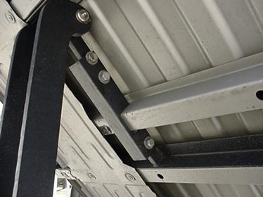
sheet metal heat shield under the passenger side of the bed. This may need to be bent down slightly to
provide clearance for the bed stiffeners to be installed. Taking PN: 9 Rear Stiffener with the pivot
bolt holes in the ends; pass it between the heat shield and bed in front of
the third cross member from front.
Mounting holes should face the rear toward cross member as shown. Taking PN: 10 Front Stiffener without the
pivot bolt holes in the ends; pass it between the heat shield and bed
behind the second cross member from front.
Telescope PN: 11 Center Bar onto PN: 10 as far as possible, rotate it up
and telescope back onto PN: 9. Align ½”
bolt holes and insert Center bar bolts with washers on hex head end.
Measure the width of the bed and mark the center of bed on both cross
members. Move the stiffener assembly so PN: 11 Center Bar is aligned with the
center of the bed.
Center bar is a notched angle iron on long bed trucks. Photo above is the long bed version with the
extra bed cross member present on 3500 model.
Use
C-clamps or quick clamps to hold in position tight against the cross member and
underside of bed. Center punch the holes
and drill 3/8” holes thru both sides of the cross member as level as possible. Insert a 3” bolt after the first hole to
ensure alignment for the other end.
Place 3/8” fender washers on the opposite side of the cross members from
the stiffeners, install locknuts. These 3/8” bolts should not be over tightened, otherwise the
bed cross members will be compressed, possibly breaking the spot welds away from
the bed.
Depending upon the configuration of the under body heat
shield, it may need to be cut or bent up toward the bed floor for hoist
clearance. Measure from the center bar to the heat
shield, we recommend 4” of clearance for the entire distance between the
stiffeners. The heat shield can be cut
with a typical jig saw using a short metal cutting blade, or using an angle
grinder with a cut-off wheel. Deburr the
edge to ensure against cuts during the hoist installation.
Find the two 2” diameter countersunk nylon (white or black) bed bumpers and the short 12mm X 20mm flat head bolts. Screw these bumpers into the front two bed mounting threaded holes.
Locate the
Rear Bed Mounts (part # 19), find the four Countersunk Flat Head 12mm X 20mm bolts
and hex wrench provided. Update:
These rear mounts are shipped pre-assembled with the Rear link and
Center link installed. The pivot bolts
are greased and tightened to proper tension. Rotate the rear link down to
install the Rear bed mounts PN: 19.
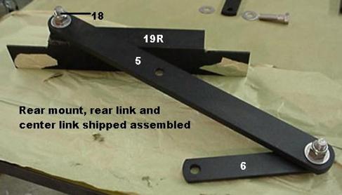
Go to the rear of the bed and install the bed mounts as shown with angle facing outside, and pivot hole to rear. Tighten flat head bolts. Rear link and center link not shown in photo, do not remove the links!
4. Main Link Assembly
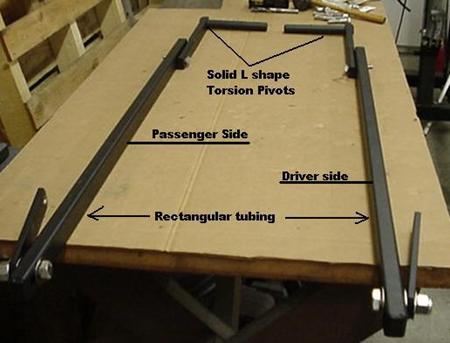
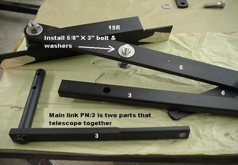
Find the Right and Left 2 piece Main Link Assembly Parts shown below:
Do not assemble yet per the above part
identification picture.
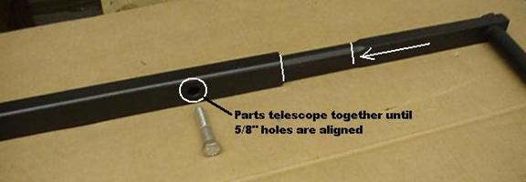
Starting with the left (passenger) 2-piece Main Link assembly, slip the torsion pivot into the rectangular tubing and align the holes for the 5/8” bolt as shown. These parts can be tight due to powder coating, use a rubber mallet if required.
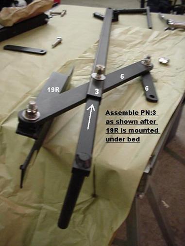
Find the Passenger Rear Link attached to the Passenger Rear Bed mount already assembled to the bed. All assembly locknuts face to the outside of the various linkages to allow clearance against the truck frame. Place a stainless washer over the Main Link 5/8” bolt. Lightly lubricate with anti-sieze and install the Main Link 5/8” bolt thru the center hole of the Rear Link closest to the short end as shown.
Photos of the assembly are shown on a bench
rather than under the truck bed.
Place a stainless washer
between the Rear Link PN:5 and the Main Link PN: 3 as a spacer. The spacer
prevents the links from rubbing together and cannot be omitted.
-------DO NOT ASSEMBLE THE DRIVER SIDE AT
THIS TIME-------
NEVER USE IMPACT TOOLS TO INSTALL STAINLESS BOLTS, ONLY USE HAND TOOLS WITH ANTI-SIEZE LUBE
Place a stainless washer over the thread end and tighten locknut. The tightness of this bolt determines the stability of the assembly. The links should move with some resistance, not freely. Do not over tighten.
Photos of the assembly are shown on a bench
rather than under the truck bed.
-------DO NOT ASSEMBLE THE DRIVER SIDE AT
THIS TIME-------
NEVER USE IMPACT TOOLS TO INSTALL STAINLESS BOLTS, ONLY USE HAND TOOLS WITH ANTI-SIEZE LUBE
Insert fully assembled Main Link 1” diameter pivot bars into the Torsion Tube Mounts.
The Pivots telescope into the Torsion Tube until the 3/8” holes align with the slots in the Tube per Diagram 2 on page 12. Insert 3/8” bolts thru Torsion Tube slots and finger tighten locknuts to allow slot adjustment.
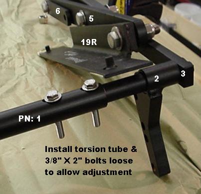
A rubber mallet may be required to insert Pivots & bolts into the Torsion Tube, it is a tight fit by design.
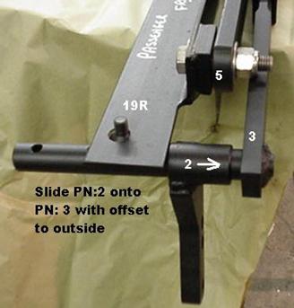
Find the driver side mount PN:2, pivot PN:3 and assemble onto the Torsion tube in a mirror image of above photo. Telescope the front half of PN:3 on driver side and assemble 5/8” pivot bolt to Rear link with lube & spacer washer same as passenger side.
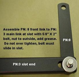
Find the bag with the two front links, two short bolts and two long bolts. The front links come pre-assembled in some cases. Assemble to the slot end of both Main links PN:3. Swing up main links on both sides of bed and assemble to rear stiffener PN:9 at the pivot hole. Use anti-sieze to lubricate pivot holes, slot, and threads.
Adjust the width of the hinge system at the torsion tube bolt slots to align the front of the main links with PN: 9 pivots. Part number 9 is the rear stiffener which should already be installed under the truck bed.
Pull PN:6, Center link, down on both sides of the hinge system.
Lift hinge system up while
rotating forward to tuck assembly under truck bed. Use tie wraps or rope around PN:3, main
link, and PN:5, rear link to hold hinge in collapsed position.
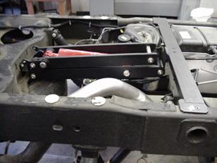
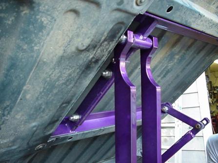
Long bed 2500-3500 assembly is shown below:
1500 hinge is the same as short bed version
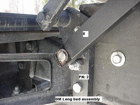
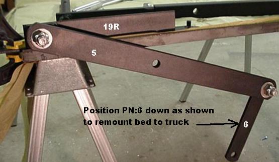
Note PN: 6 pivots on pin welded to PN: 2. Use E-clip in retaining groove.
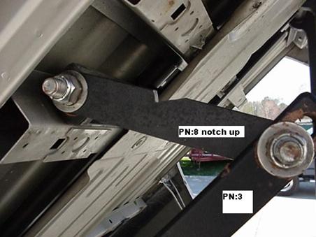
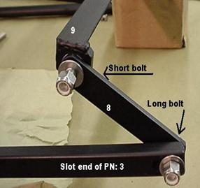
PN: 8 is installed with notch facing up to allow clearance for bed cross member. Bolt in slot on PN:3 should be loose enough to allow it to slide forward and back during operation.
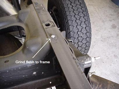
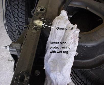
Long bed supplimental instructions
2500 & 3500
trucks with stamped rear cross member riveted to frame C-channel require the
removal or grinding flat of the rear most rivet head on the top of the
frame. After grinding flat the exposed
metal area should be protected with undercoating or paint either brush or spray
on. During grinding protect the wiring
harness with a wet rag to prevent fire or melting of plastic components.
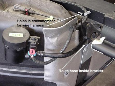
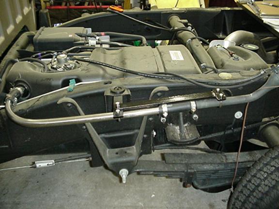
Long bed supplimental instructions
2004-up with emission controls under bed.
Emission control
hose needs to be routed inside the fuel tank bracket for hoist clearance. Disconnect from canister end forward of cross
member. Use existing drilled holes in
hoist cross member for wiring harness clips as shown.
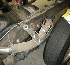
5.
Scissor Hoist Mounting
The Lower
Hoist
Position the center of the lower hoist mount at the center of the cross member facing to the rear. Check for clearance to the gas tank or other obstructions, adjust the mount to allow at least 1 ½” space to the fuel tank. It can be off center to ensure clearance, clamp it in a level position.
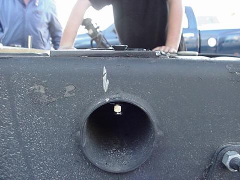
Look thru the cross member tube for pipes or wires, check backside before center punching and drilling 3/8” holes. Hold drill straight up for perpendicular holes thru the 3” dia. Tube. Do not enlarge the holes in either the mount or cross member, these must be a tight fit. It’s best to insert one bolt before drilling remaining holes.
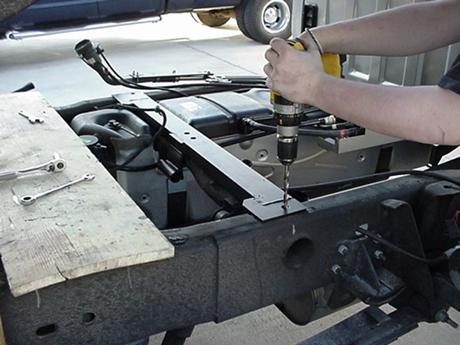
Install the long 3/8”-16 X 5” grade 8 bolts thru the center holes, use the washers on the thread end and tighten locknuts. The shorter bolts go thru the top of the frame rail and into the round cross member as shown above. Remove clamps.
Lubricate the inside of the pivot bore with copper anti-seize provided, concentrating on the lower surface.
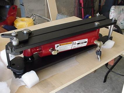
Place the
scissor hoist upside down on a table as shown.
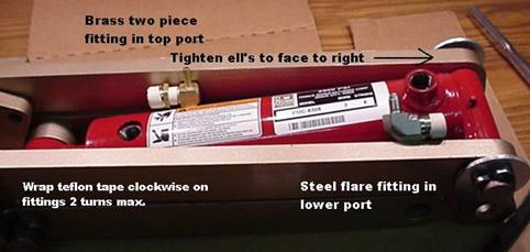
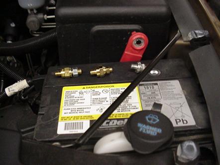
Remove the two hex pipe plugs with hex wrench provided. Inside the hydraulic parts package, find the
low pressure elbow fitting and the high pressure flare fitting. Wrap two turns of Teflon tape clockwise
around threads and install. Tighten
fittings to face the lower mount end of the hoist where you replaced the pivot
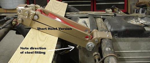
pin. Fittings
shown in photo are obsolete, upgraded fittings are both one piece steel flared elbows.
Find the lid from the crate and place it behind the lower hoist mount on top of both frame rails as shown. Turn the hoist right side up and place on the lid as shown. Remove the same pivot pin snap ring as before. Remove pin and lubricate the lower arm bores with anti-seize. Insert the pin even with the inside edge of the lower hoist arm. You will carefully use this pin, while in the lower arm, to align the hoist with the lower mount. Once aligned, simply slide the pin thru and attach the snap ring. Check the ring to ensure it is seated all the way around the pin groove. Leave the board in place supporting the hoist.
 .
.
Lift the hoist up as shown
and remove the support board.
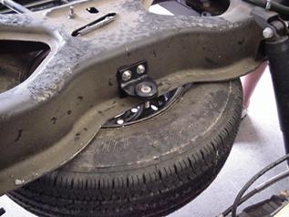
Lower the hoist carefully
and mark the center line of the hoist on the rear cross member above spare tire
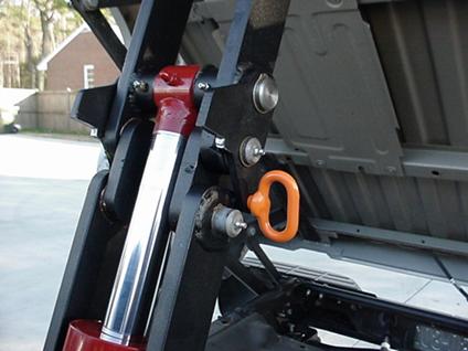
Lift the hoist back up as shown in first picture. You may need to lower spare tire for tool access. Find the hoist support bracket with hardware. Center the support bracket on the hoist centerline mark, move it down to the cross member lip, with bumper facing up. Clamp in place and drill two 3/8” holes thru rear cross member, bolt in place. As shown:
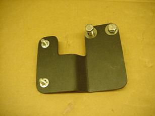
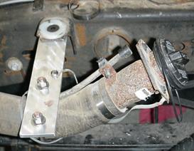
6. Pump Mount and Hydraulics
Find the
pump mount, spacer and fasteners as depicted in Diagram 6. The pump mount is attached to the front
spring mount on the passenger side behind the cab. There are two casting or forging holes
already present in this spring mount. In
some cases these holes will need to be enlarged or cleaned up with a 3/8” drill
bit. Check the alignment of the mounting holes before drilling. Install two bolts tight. Some truck kits will
be provided a pump mount without drilled frame bolt holes in order to custom
fit to the vehicle. Short bed mount left hand is
shown; long bed mount faces to the RIGHT.
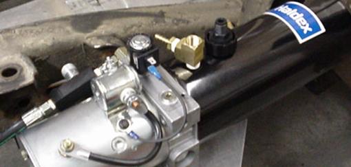
Lubricate pump bolt threads with anti-seize for future removal. Tighten to compress lock washers
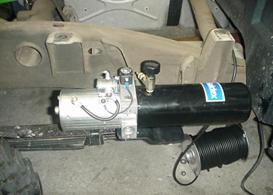
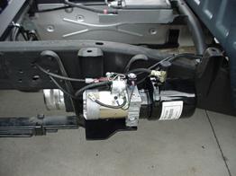
Short bed is on left, long bed is on right with larger reservoir installed. Note mount difference.
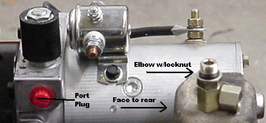
Inside the hydraulic parts package find the
high pressure hose with the valve and O-ring elbow attached. Remove the elbow and the red or yellow
plastic threaded plug on the pump hydraulic output port. Screw the male end of the elbow into the port
tight and check that the ell faces to the rear of the truck. The direction can be adjusted by the locking
nut on the male thread end. Snug the
lock nut while holding the elbow in position.
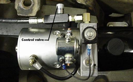
Attach the valve end of the high pressure
hose to the elbow female end. Position
the valve as shown below. Do not tighten
the valve, you will stop flow from the cylinder back to the pump. The valve only controls the down stroke speed
of the hoist for safety, up stroke is wide open. You should adjust the speed while empty to
close the bed in 20 to 30 seconds. If
you intend on lowering under load, tighten further to prevent damage to your
vehicle. If
working under bed, close valve for extra safety!
Route the other end of the high pressure hose under the frame, along the
cross member to the underside of the hoist.
Lift the hoist vertical and connect the hose to the steel fitting,
tighten. Lay the hoist down and tie up
the hose away from all hot exhaust components or sharp edges. Check for sufficient slack to allow the hoist
to tilt to vertical. Do not tie the hose
to the drive shaft ! Keep in mind the
drive shaft will be closer to the hose while the truck is under load, allow for
it now. Rubber
armored hose carrier is supplied.
Find the brass tee, brass nipple, low
pressure hose, and two circular hose clamps.
Remove the breather fill cap from the top of the pump reservoir. Wrap Teflon tape on the male threads of the
tee fitting and install in the reservoir.
Do not over tighten the tee, face the side opening toward the hoist. Wrap Teflon around the nipple threads and
install in the side opening while holding the tee in position.
Slip the low pressure hose over the brass
nipple at pump end, these are push to lock fittings. Route the hose along the high pressure hose
and tie with plastic tie wraps. Hold the
hoist vertical and attach free end to the elbow on the upper port. Trim length if required before connecting,
tighten hose fitting. Screw the breather
cap into the top opening carefully since it is plastic and could cross
thread. Do not fill reservoir at
this time!
7. Electrical Connections
Find the remote control in the pump box. If you prefer this set-up, you need to locate
the control in the cab and drill a hole for the connection ends to pass thru to
the pump. The following instructions are
intended to mount the control switch inside the center console without the remote box. If you are not qualified to make electrical
connections, please contact an electrician.
The battery should still be disconnected from the first step of the
installation. Disassemble the remote
control as shown:
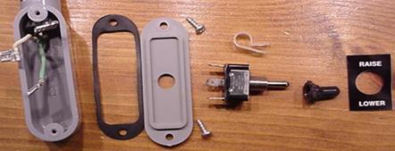
Cut off the connectors on the wires inside
the box and unscrew the strain relief fitting on the box, remove the
cable. We are keeping the switch, cable,
boot, and label, store the remaining parts.
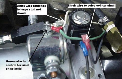
The other end of the cable has lugs to
connect to the pump, the largest ring terminal attaches to the pump motor
solenoid input power 3/8” stud. Slip
this on but do not tighten the nut. The
smaller ring terminal attaches to the pump solenoid control terminal. Install and tighten gently while holding the
stud lock nut under the ring. If the
stud turns while tightening, the internal connection could be damaged. The female slip-on terminal connects to the
valve solenoid as shown in photo. Your
wire colors may differ, please make a notation of changes from this
instruction.
White=power,
Green=control, Black=valve.
Route the cut end of the cable along the
passenger side frame under the rear of the cab.
Open the passenger door (doors), unscrew the threshold holding the
carpet down and lift or remove threshold.
Locate a suitable place to drill a hole thru the floor of the cab just
large enough to pass the control cable thru.
Check backside for any wire harness, pipes, or exhaust components before
drilling. Deburr any sharp edges with a
file, pliers, or other tool. Pass the
cut end of the cable thru the hole and route under the carpet to the front of
the center console. You may need to
remove the center console to gain access to the cable.
Once in location, strip back the cable to
expose 2-3” of wire, strip the wire end ¼”.
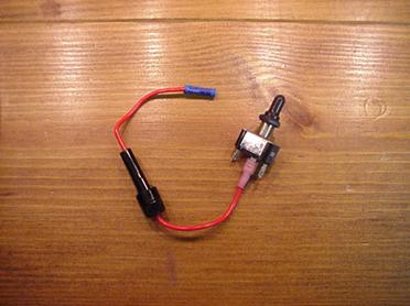
Find the fuse holder in the electrical
package and strip wires back ¼”. Find
the crimp butt connector and crimp it on one end of the fuse holder, crimp a
female 0.250” tab connector on the other end, and load it with a 7 to 15 amp
fuse. Connect the female end to the
center terminal of the switch as shown.
The fuse can also be installed at the pump
solenoid, however, it would need to be accessible while the bed is down. Otherwise a blown fuse would result in
removal of the pump to gain access.
Another method is powering the switch from the vehicle fuse panel to
provide a ‘key-on’ interlock for safety. In this case you would cut and tape up
both ends of the ‘power’ wire in the cable, run separate wire to fuse. We recommend the key interlock for
customers with low ceiling garages and/or children.
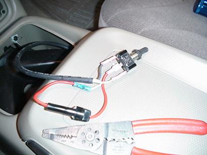
Find two more female 0.250” tab connectors
and crimp them on the stripped cable wires for “control”, and “valve” as noted
previously by color code. Crimp the butt
connector from the fuse to the “power” color wire.
Connect the two female tab connectors to the
other two terminals of the switch as shown.
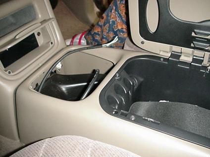
Locate a suitable flat location inside the console,
or on the dash for the switch. You will
need a ½” hole to fit the switch, check the backside before drilling. Position the switch so the “valve” color
coded wire is on the top terminal as it is installed. We recommend wrapping the body of the switch
and terminals with electrical tape to prevent disconnection due to vibration or
strains. Peel the backing from the label
and stick it on so the holes align.
Insert the switch thru the hole and tighten the boot nut carefully to
prevent tearing. You may omit the boot
if the location is normally dry. The
switch should spring return to center when actuated up and down.
Use tape or
silicone sealer to seal the hole in the floor of the cab around the wire.
Secure excess cable and re-assemble the truck interior
parts.
Locate
the 20 feet of welding cable and attach the lug end to the pump solenoid 3/8”
power terminal and tighten with same care as control terminal. Route the cut end along the passenger side
frame under the cab and into the engine compartment to the battery. Keep away from hot exhaust and suspension
components, tie with tie wraps provided.
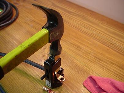
Find the large copper battery lug and CM-20 Crimpler Tool, insert the
lug into the spring loaded tool as shown.
Strip back the cable ½” and insert into the lug, hammer the top of the
tool several times while holding the wire tight inside the lug.
Pry the factory battery cable bolt out of the
factory cable with a small screw driver.
Find the double ended battery cable bolt w/nut and install in the
factory cable boot with nut end to the outside.
Two types
shown above with factory bolt.
Do not connect the battery
at this time.
8 Remounting the bed: Lift the scissor hoist and
remove the support board, lower the hoist gently. Remove the snap ring from the
passenger side of the upper hoist pivot pin (part 8, diagram 5). Remove the pin to prevent the center bar from
hitting it as the bed is installed.
Clear all tools and loose
parts off the frame and under the truck.
Raise the bed with the engine hoist and remove the sawhorses. Get assistance from two other people to help
move the bed back over the truck frame. Tuck
and tie the fuel filler neck out of the way. Use care not to collide the front of the bed
with the rear of the cab or window.
Position and gently lower the bed while checking for clearance at the
front, side to side, and at the rear bumper.
Do not crush the electrical plugs from the bed. The ends of the rear torsion bar pivot mounts
should be outside the rear frame rails as you land the bed back on the
frame. The upper arms of the scissor
hoist may hit the underside of the bed since it’s hanging out of position. The rear bed mounts should land on the top of
the frame. Using a screw driver or
tapered punch, look under the rear driver side wheel well and align the rear
pivot mount holes with the two bumper mount holes. You may need to release the main arm rope or
tie wraps and adjust the position of the hinge.
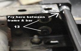
Insert the 1/2” bolts PN:13 with washers, put locknuts on finger
tight. Repeat for passenger side as
shown below (bed not shown in photo).
Once all four bolts are installed, tighten all locknuts.
At this point the bolts
holding the bed hinge system to the frame should be tight enough to prevent
movement of the mounts. However, the
installer should be aware the bolts may need to be loosened or removed to
adjust bed to cab alignment during testing.
Let the hoist down to disconnect the rear two
chains. Connect the loose chains to the
forward bed tie downs. This doubles the
number of chains at the front of the bed for safety during the following steps.
Begin to raise the bed using the hoist with
doubled chains. The rear of the bed
should raise by itself since all hinge connections are complete. Check the front of the bed to cab clearance
as the bed moves up, there should be at least ¼”. Raise the bed as high as possible and place
the lid from the hinge crate under the bed as a safety prop.
Retrieve the upper hoist pivot pin, snap ring
and snap ring pliers. You will need an
assistant to help raise the hoist to vertical and extend the arms. Lubricate the arm bores and insert the pivot
pin half way FROM THE DRIVERS SIDE. Lift
the hoist vertical and extend the arms till the pin aligns with the pivot bore
per below. Insert thru the center bar
and other arm bore while holding the weight to prevent misalignment. Install snap ring on passenger side of pin,
ensure it is fully seated.
Purchase three quarts (four quarts for large reservoir long bed) of Dextron automatic
transmission fluid and fill pump reservoir thru top opening of brass tee with
small funnel, replace cap carefully. In
hot climates we recommend 10W-30 SAE motor oil or 30W hydraulic jack oil rather
than Dextron fluid.
9.
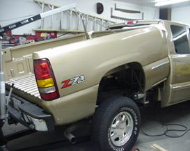
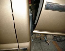
Body Alignment: Ease
bed down with hoist while checking bed to cab clearance. Look along both sides of the truck body from
the front fender. On the side the bed is
indented, loosen rear torsion mount and under frame mount bolts. Pry the torsion bar to the rear as
far as possible, then tighten bolts while holding pry pressure. It may help if another assistant pushes the
bed from the opposite front corner, check the body fit again. If it’s still indented, loosen the opposite
side rear torsion bar mounts and pry the torsion bar forward while
pressing the bed into position. If
the bed will not align with the cab to your satisfaction, you may need to
enlarge the frame holes at bolt 13 in the direction required on each side.
Once the body is aligned, tighten the bolts
on the mounts evenly, this secures the alignment at another location. We will check this alignment again after
testing hoist operation.
10.
Testing Operation: At this point all hinge bolts should be
tight, the scissor hoist installed with hoses, hydraulic reservoir filled,
switch installed and wired, and battery ready to connect. The fuel filler neck should be tied out of
the way. The plugs for the tail lights
should be disconnected and out of the way of the bed travel. Unhook the bed chains from the engine hoist
only, back the hoist away.
Please wear safety glasses for the
next step.
Connect the factory battery cable using the
double ended stud. Touch the side of the
stud (not the threads) with the pump power cable to check for shorts &
arcing. Alternately use an ohm meter to
check resistance to ground on the cable.
Use anti-seize on the stud threads and install the cable, keep the hood
open and wrench nearby to disconnect in an emergency during testing.
--------Back the vehicle
out of a garage with a ceiling height under 12 feet.-------
While operating the dump system, please do not hold the switch in the on position at the top of the stroke. This causes the relief valve to open at full pressure, and re-circulate hot compressed fluid thru the pump when the reservoir is almost empty. This will considerably shorten the life of the pump. Additionally, you will fully pressurize the cylinder, which could overload the piston seals or scissor mechanism causing damage.
Switch the pump on to raise the bed, let off
the switch at the top, the pump should stop and hold the bed up. Now lower the bed to bleed air out of the
cylinder. Raise bed again and check for leaks on pressure hose and pump
fittings. Hook the bed chains back up to
the hoist before working on the pressure hose.
Recheck alignment of the bed and cab after 4-5 cycles. Set your flow valve for a 20-30 second down
stroke. In cold weather the valve may
need to be opened further, hot weather requires a tighter setting.
Ensure hoses and wires are tied up
away from exhaust system and drive shaft, check for pinching or chaffing
against sharp objects, correct routing,
Grease the mechanism at all grease fittings
with 1 or 2 shots of General Purpose EP-2 grease. Wipe off excess.
11. Fuel Filler Modifications: There
are two options to modify the fuel filler neck. Always work on the
fuel system outdoors so vapors don’t accumulate. Do not smoke, create heat, or sparks while
working with the fuel system. Provide
proper fire extinguishing equipment and/or a charged water hose nearby in case
of accident.
a.
Option One: Disconnect the filler
hose, flush it with water and cut the steel neck short enough to fit under the
bed while down. You will also need to
cut the rubber hose. Use dishwashing
soap on the hose to assist re-connection, tighten all hose clamps. This task is best accomplished after the
bed is replaced on the truck to check for clearances. Keep in mind you will be required to raise
the bed any time you need to fuel the truck.
We do not recommend this option, however, many customers are pleased
with this filling method.
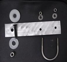
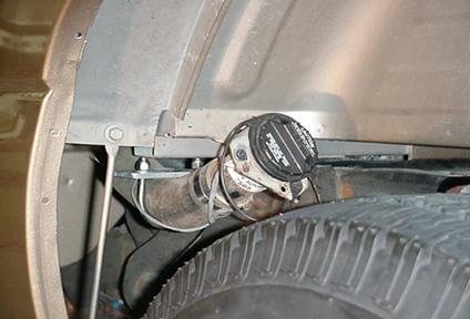
b. Option Two: Find the 2” elbow, hose clamps, and aluminum
flat bar with the stainless ‘U’ bolt attached.
This flat bar is attached under the second bed mounting ear
behind the cab, only the washer and bolt are above the top surface. Use a washer under the flat bar and tighten.
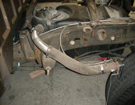
The rubber filler hose must be cut in half to
insert the elbow as shown above. The pipe
elbow supplied is longer than required so the customer can cut and fit to clear
the bed when down. We recommend using a
new razor knife to cut the rubber hose about 6” from the tank. Loosen the hose clamp and remove it from the
tank first. When installing the 6”
section, turn it 180 degrees to face down rather than up to give the elbow some
slope into the tank. Cut and fit the
elbow using a hack saw well away from any gasoline vapors. Deburr the sharp edges and clean the metal shavings
out of the elbow. Slip the two hose clamps over the hose ends. Use dish soap on
the inside of the rubber hoses to help install the pipe. Use the ‘U’ clamp to hold the filler neck up
in the wheel well. Attach grounding
strap if required.
Do not lower the bed yet.
Long bed supplimental instructions


Note extra fuel pipe support bracket and U-bolt. Bend brackets to provide slope to tank as
shown. Ensure ground braid is connected
to frame or bracket bolt.
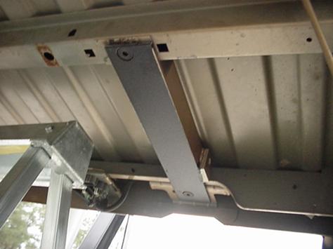
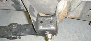
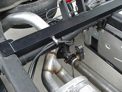
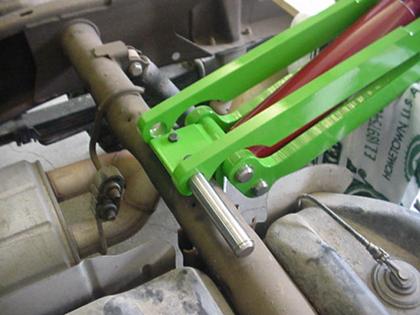
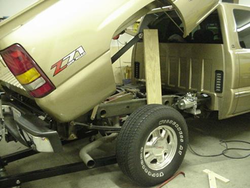
At this point the fuel filler neck task
should be complete. In some trucks the
fender support bar needs to be removed as shown in the photo below.
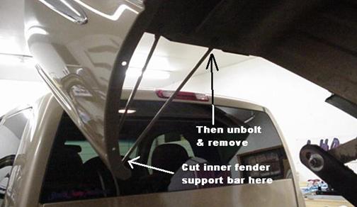
After it’s out
of the way, lower the bed while observing the filler neck for clearance.
Take care when filling not to overflow
the filler neck since fuel can back up with the near level slope.
Attach your cap lanyard to one of the screws
that held the plastic shroud.
Ensure there is clearance for the
tire travel when the truck is loaded not to hit the filler neck.
Raise the bed and check the length of the
taillight wires to reconnect the plugs.
You may need to unfasten some harness clips to gain length. Route the wires to the inside of the Torsion Tube
and plug in. Check for clearance as you
cycle the bed up and down. Install the
tailgate.
12.
Vibrator installation (optional accessory): The
vibrator is a simple DC electric motor with offset cam type weights inside that
cause 80lbs. of rotational vibration, at 4000 RPM when running.
Locate the vibrator parts and mount. Raise the bed and find a place the vibrator
will fit under the front of the bed on either corner. It works best when positioned parallel to the
rear axel, and turning clockwise when viewed from the driver side.
Mark the location and lower the bed to check
for clearance when down. Keep well away
from the hot exhaust, hydraulic pump, and fuel tank. Remove any plastic bedliners from the bed in
order to drill holes thru the bed floor or sidewall. Hold the vibrator in the location selected
and center punch the hole locations.
Remove vibrator, wear safety glasses, and drill four 3/8” holes, check
the backside for obstructions prior to drilling. Find the square vibrator mount with the
rounded edges. The round edges face down
toward the vibrator when installed.
Insert bolts thru the vibrator, place spring washers on back side of
the vibrator. Place the unit in
location with bolts thru the bed.
Install mount with rounded edged toward unit, start all nuts by hand,
tighten the bolts with tools.
There are separate detailed installation
instructions with the vibrator. Route
the cable to the center rear of the bed and secure. You may need additional cable to reach the
switch location, purchase 16 or 12 gauge two or three conductor portable cable
(extension cord) at a hardware store.
There are two switches in the parts bag, one is a toggle the other is a
momentary push button. We recommend the
push button for dump truck applications.
Press and release for 2-5 seconds, the vibrator will continue to work
while coasting to a stop. Check bolts
and sheet metal regularly if you use the vibrator.
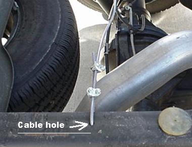
Scissor Hoist Support
Cable: On some model trucks, the scissor hoist may
hang down far enough to hit the top of the rear end axel or spare tire. In this case please find the 4 foot cable and
four clamps and install to support free end of the scissor hoist. Some frames have existing holes that can be
utilized for this cable. If not, you
need to drill a ¼” dia. Hole approx. 3” behind the center of the rear axel on
the top frame web as shown:
.
The cable should be installed slack and adjusted tighter after testing to
ensure it holds the free end far enough away from the axel housing. Plastic covering the
cable should be stripped off before clamps are installed.
III. Maintenance, Cleaning, and Lubrication
1. Safety Pin:
The safety pin should be sprayed with WD-40 or other light lubricant
then wiped dry to prevent attracting dirt.
This pin is only used while working under the bed and is intended to prevent
injury due to failure of the hydraulic cylinder to hold pressure. It will lock the scissor in the up position
when fully inserted through the scissor hoist stop block, lower arm, and
channel hinge. It can be used from
either side of the scissor when in the fully extended position. Do not rely on the safety pin to hold a
fully loaded truck bed, it should only be used when the bed is empty. Make a habit of inserting the pin whenever
the bed will be up for any longer than a minute.
If you
lose your pin, contact us ASAP for a replacement to be shipped.
2. Hydraulic System: Use GP EP-2 grease at all grease fittings,
wipe away excess. The piston rod of the
cylinder should be sprayed with silicone lubricant every three months. Other lubricants can attract grit that would
bypass the seal. The scissor pins &
bores can be lubricated with EP-2 grease every three months. We use the copper anti-seize during
installation which acts as a long term lubricant due to molecular bonding of
the copper to steel. It creates a copper
bushing under load over time. Do not use
high pressure water to clean the scissor hoist, cylinder, or hydraulic
pump. Simply wipe clean with a rag. Correct any hydraulic oil leaks when they are
discovered. The hydraulic pump &
cylinder is not repairable by the customer, contact us for replacement. Under normal use, the lifetime of these
components is over five years. The
hydraulic fluid should never need to be changed unless contamination is
obvious.
3.
Hinge Mechanism: Use GP EP-2 grease at all grease fittings, wipe away
excess. Use 3 in 1 oil on all other
pivots, it will penetrate to the bearing surface, wipe clean. Every six months, use
a wrench to turn the pivot bolts 90 degrees clockwise. This will spread any wear on the bolts evenly
while tightening the locknuts. Check for
loose fasteners on all mounts.
Any unusual noise during operation should be investigated and corrected
as soon as possible. Stainless steel has
the unique property called ‘work hardening’ where the surface of the steel will
become harder after repeated use. The
pivot bolts should last literally forever with proper maintenance and
occasional lubrication.
4.
Electrical system: Check battery
cable for corrosion at both ends, clean with water and baking soda, spray with
silicone lube. Check for loose
connections on control cable every three months. If the switch ‘feels’ different during use,
it may need replacement. If the pump
won’t start, it’s possible the solenoid may need replacement. The solenoid is a standard automotive type
that can be purchased at any auto parts store.
Check your ground connections also!
Never use paint
thinners, carburetor cleaners, or other solvents to clean the components of the
system. Only use car wash soap and
water.
Never spray high pressure water on the pump
or hoist.
Contact us for
questions & parts:
Stealth Dump
Trucks, Inc. (757) 890-4888
sales@stealthdumptrucks.com
Congratulations!
You completed
the ‘Over the Bumper Dumper’ installation!